Replicating the brake bracket
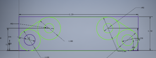
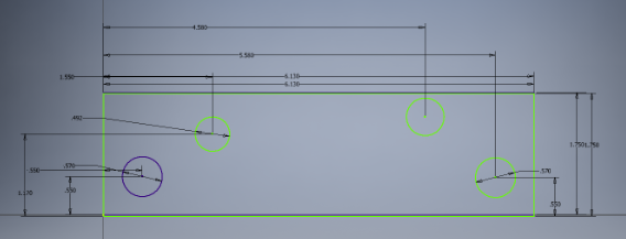
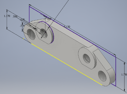
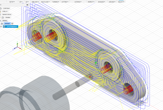
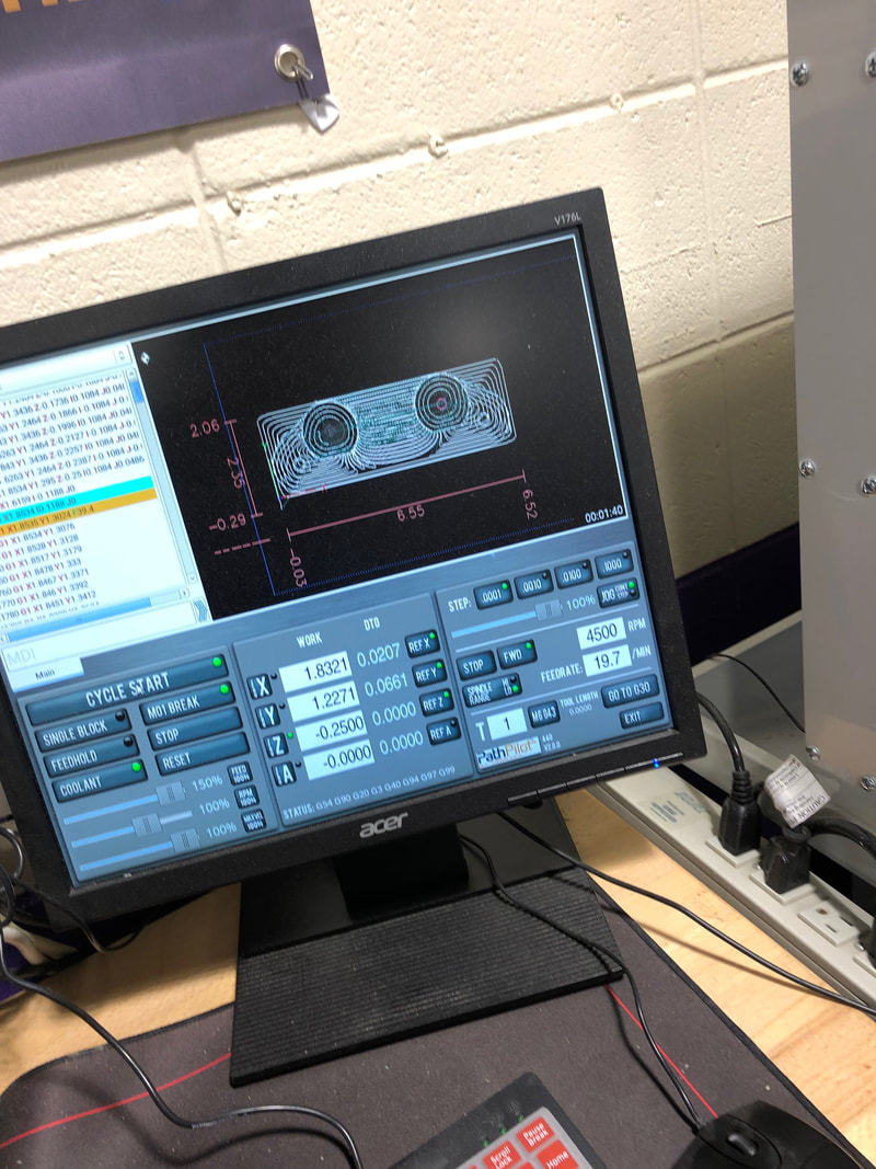
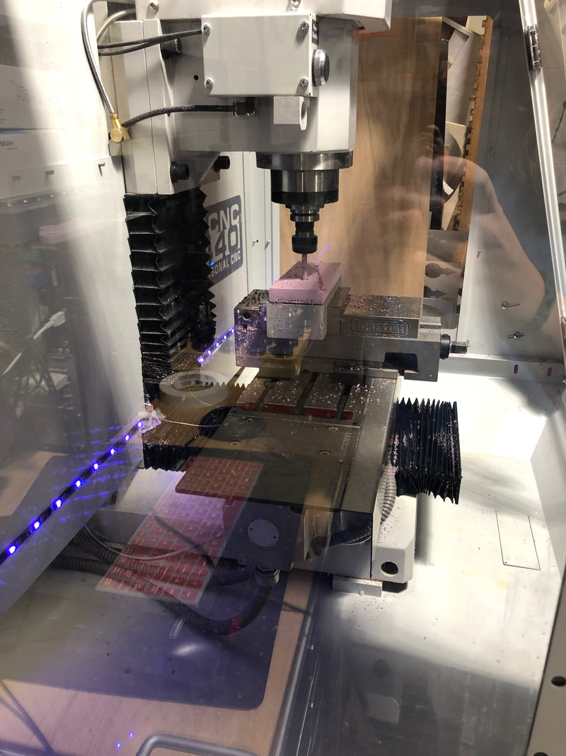
I began by looking over the handout with the correct dimensions. I used inventor to sketch the outside, cut through circles, and rounded edges. Then I used the trim tool to get rid of the excess lines. I extruded it and then made the raised circles. Once I was finished it looked like so. Then I uploaded it to Fusion 360 and began setting up my tool path. I set the stock box point to the bottom left corner and set the stock to 6 x 2 x .75 inches and putting the offset to zero. I then clicked on 3D Adaptive Clearing and set the tool measurements (flat end mill, diameter .25", body length 2", and speed 5000 rpm. Under the passes tab I changed the step down to .25". and stock to leave to zero. Then my tool path looked like this below. I went to the mill and taped my foam to the platform set up. Once I loaded it from USB copied G code and zeroed x, y, and z I started it.
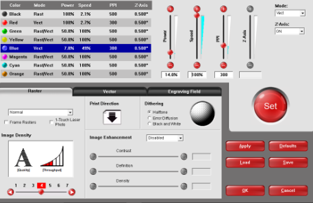
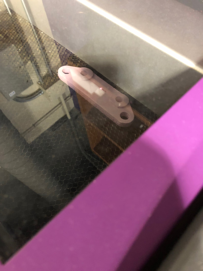
After this I laser engraved my name onto the brake bracket using the same document as the maze. I selected blue vector and changed the power to 14% and hit ok.
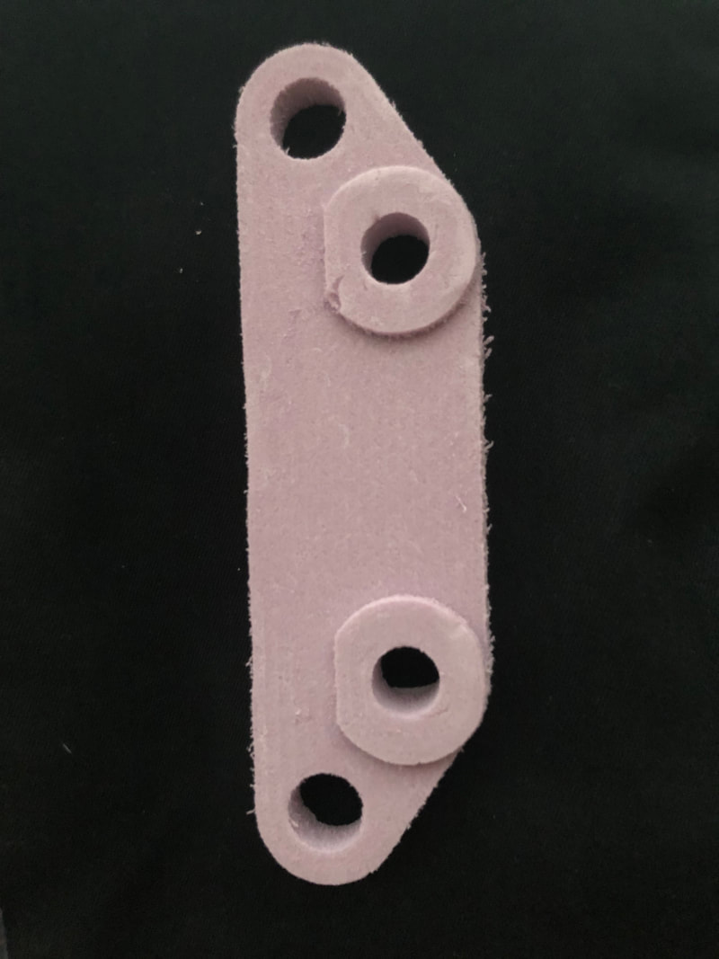
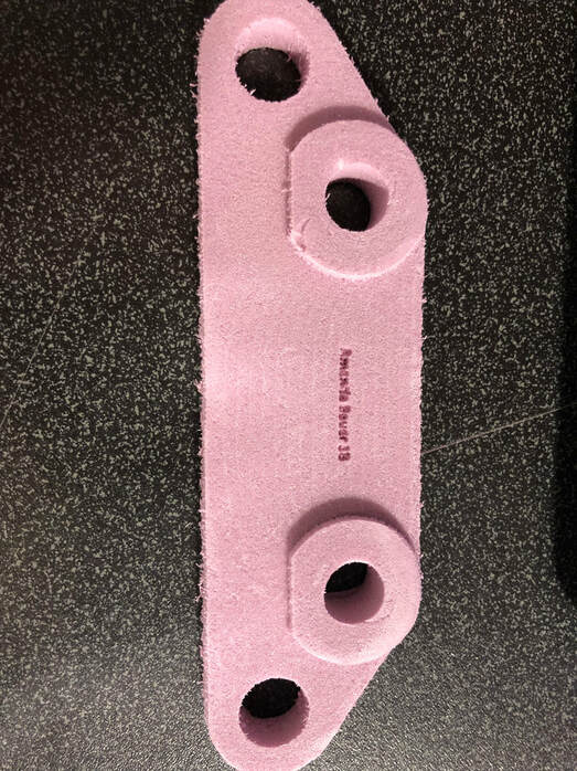
Below is the final product.
In this project I learned how to use fusion to create a 2D design and how to use the CNC Mill. The mill was a lot like the router which was easy in setting up the bit in line with the stock box point. The only thing majorly different from the two that I learned was the software. Here I had to load the file onto the computer and zero out all planes and load G code. There is also not much difference in the overall cutting out aspect as well which was cool. I was pretty comfortable using this machine as it was pretty self explanatory. I can't wait to start working on my final clock project!
